A combined-cycle power plant uses both gas and steam turbines together to produce up to 50 percent more electricity from the same fuel than a traditional simple cycle plant.
Typically, a combined-cycle power plant comprises of gas turbine generators fitted with either a Once Through Steam Generator (OTSG) or a Heat Recovery Steam Generator (HRSG) and Steam Turbine(s). Water is run through an OTSG or a HRSG that captures exhaust heat from the gas turbine that would otherwise escape through the exhaust stack. The HRSG or OTSG creates steam from the gas turbine exhaust and delivers it to the steam turbine. This steam can be in the form of and include any of the following: high pressure, various intermediate pressures, and low pressure. The steam turbine sends its energy from the steam to the generator drive shaft where it is converted into additional electricity.
As such, each plant will require steam blows on the steam piping prior to startup and operation to remove any rust, debris, scale, or greases which can potentially damage or reduce the efficiency of the steam turbine. This can cost the plant owner millions in lost efficiency and/or down time if not properly performed.
The steam blows are performed using low-pressure continuous steam blows where the steam is blown at pressure, temperature, and flow rate conditions that can be significantly lower than the operating conditions. These blows are designed to produce conditions in which the force created during the steam blow meet or exceed the forces during maximum operation conditions. The comparison between the cleaning force during the steam blow compared to the force generated during the maximum operation conditions is known as the cleaning force ratio (CFR). Steams blows are designed to have a CFR greater than 1. Due to the sensitivity of the steam turbines, the quality of the steam blows is typically measured using targets which are inserted into the path of the steam during the blow to measure how clean the pipe is. Specifications of how clean and the number and size of impacts on the target are typically provided by the turbine vendor.
Combined cycle plants can contain one or several gas turbine generators with OTSGs or HRSGs and can feed one or multiple steam turbines. They can also have multiple forms of steam such as high pressure, intermediate pressure, and low pressure steam feeding the steam turbines. Due to the temperature gradients inside the OTSG or HRSG, when multiple forms of steam are present, they will need to be run and cleaned at the same time. When multiple gas turbines with OTSGs or HRSGs feed into a single turbine, piping configuration must be taken into account during the steam blows to ensure sufficient cleaning occurs in each section of the piping. This may require multiple stages to perform the steam blows.
Unlike basic steam boiler plants where the steam properties during the blow are controlled using throttling valves or devices, the control of steam properties during each stage of the blow is controlled by controlling the rate of water feed to the OTSG or HRSG. This must be coordinated with the load each gas turbine is set at to ensure the steam properties are such that they meet or exceed a cleaning force ratio greater than 1 or the client specified requirements. When multiple pressure forms of steam piping need to be blown (i.e. high, intermediate, and low pressure), attemperating of the steam to meet the required blow conditions and remain within the steam piping designed maximum expansion limits may need to be performed.
Thermal cycling, a technique that aims at expanding/contracting the pipeline to a point where mill scale and particulate matter is dislocated from the pipe internals and carried away in the steam flow, is used to add efficiency to the cleaning application. This is performed by either using the attemperating systems to cool the piping temperature down while continually blowing or shutting down the steam blow all together and allowing the piping to cool.
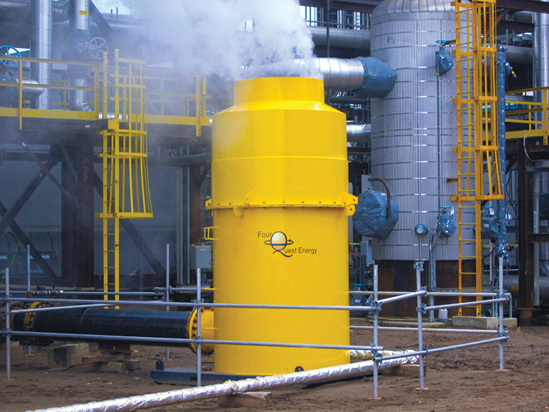
Temporary steam blow piping must be designed as per ASME B31.1 and be able to handle to maximum blow conditions which can occur during the steam blow. The temporary steam blow piping is run from the blow point on the steam piping to an ended collection tank know as a silencer. The silencer functions to reduce the sound produced by the steam blow using muffling technology, collects debris from the piping during the blow, and redirects the exhausting stream upward in a controlled manner to reduce any forces on the piping during the blow and to direct the exhaust away from personnel and equipment in a safe manner. To further reduce sound during the steams blows, quenching is used to bring the steam temperature down to saturation prior to entering the silencer at the end of the steam blow line. This allows other site activities to continue onsite during the steam blow in a safe manner with minimal hearing protection requirements and closed off areas.
As most combined cycle plants are not designed to have a large reservoir of water and the water used during the steam blow is exhausted to atmosphere in the form of steam, additional water sources may need to be brought in for the steam blowing. To facilitate the water requirements for steam blowing, a temporary water source with boiler feed water quality will likely need to be used. These can be generally quite expensive, so designing the steam blows, including feed water, attemperating water, and quenching water with the least amount of water requirement is very important. The steam blows need to use the least amount of water possible while still meeting a CFR greater than 1.
With all these design factors considered a significant amount of engineering and planning around the operation of the gas turbine(s) during the steam blow must be performed before the steam blows can proceed. This is a service that we specialize in.