January 9, 2017
- Oil & Gas
- Canada
- Pre-Commissioning
Pre-Commissioning and Commissioning a Northern Alberta SAGD Facility
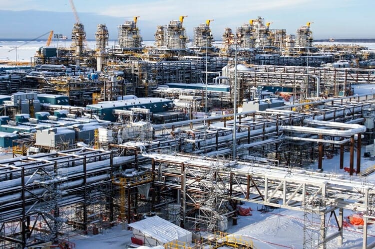
FourQuest Energy was awarded the full pre-commissioning and commissioning work scopes at a Northern Alberta Oil Sands SAGD facility. During our time onsite, we became an integral part of the C&SU team working to ensure a successful, on time start up.
Pre-Engineering:
Initially, our personnel performed pre-engineering. We had two engineers working in conjunction with our client’s team, early in the design phase performing a high level analysis of the pre-commissioning activities. Once our engineers were onsite, they began working with our clients engineering team not only on pre-commissioning procedures, but also on an audit of the relief safety alarm system, and on the commissioning and start up sequence for the glycol system. As construction began, our engineers joined the clients C&SU team where individual system packages were reviewed, field verified, and revised accordingly based on real world conditions.
When pre-commissioning started, our engineers received new scope additions to develop procedures for, and were able to assist our operations group with the overall execution of the existing scope and the scope additions. The previously completed pre-commissioning procedures were revised based on new C&SU recommendations and updated real world scenarios (ie. scaffolding blocking access, seasonal changes, temperature changes, craft support availability). Engineers also conducted field supervisory roles during pre-commissioning activities while providing continual, ongoing technical support.
Air Blowing:
Air blows were conducted on numerous process and utility systems throughout the entire facility. We maintained 2-3 air spreads during the pre-commissioning stage. Air blowing specifications included dewpoint, borescope inspections, and targets. Numerous air blowing methods were utilized to achieve these specifications. These methods include:
- Decompression blows which have the system pressurized to the engineered pressure, before being quickly released from one end of the piping. This rapid depressurization of the piping removes loose debris from the piping.
- Pulse blows which are performed where access is restricted at the exit of the piping. Air is compressed in a vessel and then rapidly release into the system to remove loose debris.
- Continuous air blows maintain a constant air flow, at the required, calculated velocity, to remove debris from small diameter lines.
Oil Flushing:
Oil flushing was conducted on the HP BFW Pumps, the OTSG air blower lube oil system, and a well pad process gas compressor. All oil flushing was conducted to the appropriate ISO cleanliness specification for each system. During the execution we used our FS-2000 and FS-4000 flushing skids. These flushing skids are capable of providing 2000L/min and 4000L/min respectively. Each skid is equipped with a pump, heater, filter system, and incorporates a reverse flow manifold to allow for flushing the system in both directions to remove any pockets of air or particles trapped in dead zones that would be missed by only flushing in one direction.
Prior to some of these oil flushes, a full 3 phase chemical clean was conducted on carbon steel lines. This chemical clean was necessary to remove built up rust, greases, and construction debris.
Chemical Cleaning:
Chemical cleaning was performed on the HP Pump suctions and discharge, and the 700 m3 BFW system. The BFW system chemical clean included the LP pumps, through the heat exchanger banks, to the HP pumps. This 700m3 system volume is a significant system size to perform this type of scope on in a single set up.
Single fill, three phase chemical cleaning was performed on these systems. The first phase consists of a degrease to remove oils, varnishes, and greases left behind during construction. The second phase is an acid wash and corrosion inhibitor that will remove rust and mill scale from the system. Finally, the system undergoes a passivation stage which produces a gamma hematite layer to provide temporary protection for the system while it awaits commissioning.
Glycol Filtration:
We completed a flush on the glycol heat medium system. This 1200m3 system required an extensive set up of equipment including 6 x 12” x 8” pumps, 2 x tri-eighteen filter skids, a 16” supply manifold, and 2 x 8 million BTU heaters. This system was circulated through various loops of the piping to provide sufficient velocity through all branches to remove particulate.
The system circulation was continued until the cleanliness specification was met. This cleanliness specification was confirmed once 12 hours of circulation had occurred without significant pressure change with 5 micron absolute filters.
Highlights
Pre-Engineering and Air Blowing
Lube Oil Flushing and Chemical Cleaning
Glycol Flushing and Reverse Osmosis provision for BFW system
Line Heating and Pond Thawing
Tank Heating and Tank Filtering
High Velocity Flushing and Water Chlorination